Harmonics and Their Effects
Understanding the Cause, the Consequences, and the Cure
When it comes to the electrical phenomenon known as “harmonic distortion,” ignorance is no defense against costly damage to equipment and financial penalties, even service disruption from the power supplier. Yes, what you can’t see can hurt your company’s bottom line.
In one sense, harmonic distortion is an inconsistency in the electrical supply. It occurs when the waveform of the alternating current on the grid is subject to volatility and gets distorted. The cause is often the equipment that is being powered by the grid. The bigger the equipment—for instance, a variable frequency drive has a bigger impact than a light bulb—the greater the impact on other equipment and power distribution upstream on the power grid.
And while you may not be able to see such distortion as it happens, make no doubt that your power supplier can and will insist that your company fix the problem and, possibly, pay fines. But don’t wait for your utility to let you know there’s a problem. Especially if your company draws a large amount of power, being proactive in both the detection and prevention of harmonic distortion is a must.
Harmonics Discovered and Defined
While often misunderstood, harmonics as they relate to electrical power supply are relatively simple. First, we should note that in North America, power companies produce power at 60Hz (see figure 1). Harmonic distortion—which is basically defined as an integer multiple of the fundamental frequency—occurs at multiples of that 60Hz and creates problems in the distribution network, particularly in magnetic devices, such as transformers as well as relaying devices and meters in substations and at service locations. The problems can manifest themselves in the form of failure of control devices or of the devices themselves, causing power outages and general destabilization of the power grid.
Harmonics are not a new phenomenon. In an article entitled “History of Harmonics in Power Systems,” author E.L. Owen highlights that early in the life of AC power generation the Thomas-Houston and Edison General Electric companies promoted generating power with high frequency of 125, 133, or 140Hz. (Interestingly, in 1892 these two companies merged to form General Electric.)
It was in 1890 that the first long-distance power transmission line was installed, transmitting power at 133Hz over 12 miles. Just three years later, one particular customer that the General Electric (G.E.) Company serviced was experiencing excess heat on one of its motors. The power provided was produced at 125Hz.
According to Owen’s article, the newly formed General Electric hired the genius mathematician and electrical engineer, Charles Steinmetz from Germany, to investigate the problem. By working with the customer and using the tools he had available, he was able to ascertain that harmonics were involved due to the high frequency generation output from the plants over the longer distance lines.
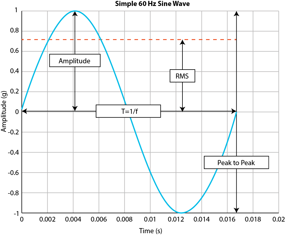
Figure 1: 60Hz Sine Wave
This harmonic issue became known as “line-resonance,” and Steinmetz’ finding caused G.E. to lower their output frequency of generation from 125Hz to 62.5Hz in order to minimize the harmonic affects. Figure 2 shows the waveform that Steinmetz generated using his tools in 1893 (keep in mind this was before oscilloscopes). This incident is widely considered the first time harmonics were observed in power generation—just three short years after the U.S. installed its first long distance power lines[1].
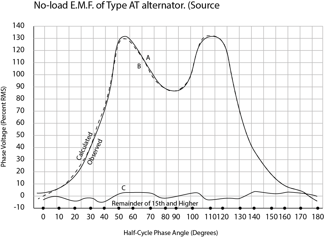
Figure 2: No-load E.M.F. of Type AT alternator (calculation of the harmonic derived by Steinmetz in 1893) 2
[1] Owen, E. L. (1998, January/February). A History of Harmonics in Power Systems. IEEE Industry Applications Magazine, 6-6.
Sources and Effects of Distortion
Since that discovery, power companies have implemented the necessary measures to protect against harmonics, and their monitoring and protective equipment has only gotten more sophisticated. Back in 1893, Steinmetz found the power utility itself was the cause of harmonics. Currently, however, the power utilities have largely eliminated their responsibility for harmonics on the grid.
Today harmonics by-and-large come from the customers of power generating utilities. The non-linear loads — aka harmonic distortions — are from motors, variable frequency drives (VFD), DC power supplies, computers and uninterruptible power supplies, and many other solid-state devices. When these components are used, they send high-frequency signals back onto the power grid.
The high frequency signal is what distorts the fundamental sinewave — this is harmonic distortion at its core. In figure 3, the fundamental sinewave is the ideal sinewave generated by the power utility, a customer’s load generates 3rd and 5th harmonics (two of many integer multiples of the fundamental frequency) that cause the distorted waveform for all upstream customers on the point of common coupling (PCC).
Yet, power grids are not all affected by harmonics in the same way. The available power at the power source, and how much load is being drawn from that power source, determines how much the harmonics will affect the grid’s waveform. A VFD connected to a motor powered from a small 5500-watt generator will have more of a harmonic affect than if it was powered from a source with 800-megawatts of capacity. To put it another way, imagine your VFD load is like a person doing a cannonball into a body of water. If the person does a cannonball into a kiddie pool, the effect on the entire body of water will be greater than if the person performs the cannonball in the middle of the Atlantic Ocean. IEEE 519 – 2014 gives recommendations on the amount of harmonics acceptable for a given load compared with its available power on the grid.
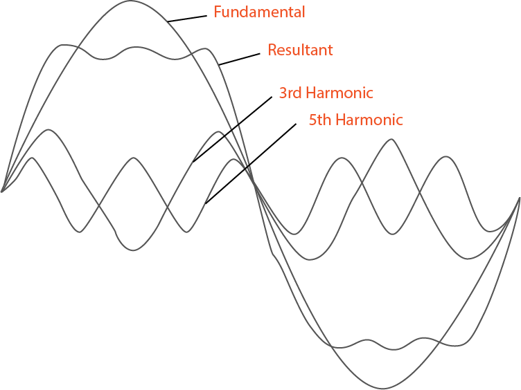
Figure 3: Fundamental wave, harmonics and the composite (resultant wave)
Defining the Relationship Between Supplier and Customer
For utility companies, harmonics cause adverse effects on power transmission and power generating equipment. For customers, they cause increased energy costs by diminishing equipment performance through heat losses and shortening hardware life. Since the generating utilities need to safe guard the quality of power they are supplying to all of their customers, they draft contracts with their industrial customers. The industrial customer is expected to use power as described in the contract. Failure to maintain agreed upon levels of harmonics can result in violations.
In the oil industry, power companies typically want their customers to maintain 5% distortion or less with an absolute max of 8%. It is important to remember that just because a customer might be ignorant of harmonics and their effects, the power company will still hold that customer responsible for the harmonics his/her equipment produces if the harmonics are outside of their allowed range.
Whether a customer experiences fines for power violations, increasing energy costs or replacing damaged equipment, harmonics are an expensive problem if left unchecked. Fortunately, there are solutions and SPOC Automation is an industry-leader in harmonics mitigation. We offer analysis of a site’s harmonic effect and guidance as to which solution is best.
Mitigating Damage from Harmonic Distortion
Harmonic code compliance becomes more critical every day. At SPOC, we focus on the entire system, providing a variety of solutions to ensure that you continue running reliably, efficiently and in compliance of IEEE519 and EN-6100-3-2.
Inductive reactance, passive filters, active filters, 12 or 18 pulse drives and active front end are all solutions that help mitigate harmonics.
Our low-harmonic drives keep you running reliably, efficiently and in compliance
Harmonic drive compliance becomes more critical every day. At SPOC, we focus on the entire system, providing low-harmonic drives to ensure that you continue running reliably, efficiently and in compliance of IEEE519 and EN-6100-3-2.
Inductive Reactance
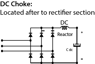
Using inductive reactance is a cost-effective way for lowering harmonics. By placing a 3% AC input reactor in line with the incoming power to the rectifier or by installing a DC reactor (choke) after the rectifier, the distorted current is lowered to around 35%. Without these devices, the harmonics can be typically up to 80%. Inductive reactance is a simple and inexpensive first step towards reducing harmonics and should be considered a minimum practice for any drive. As a side benefit, the reduced harmonics reduce the incoming amperage to the VFD, reducing heating and extending its expected life.
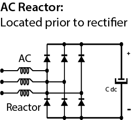
Passive Filters
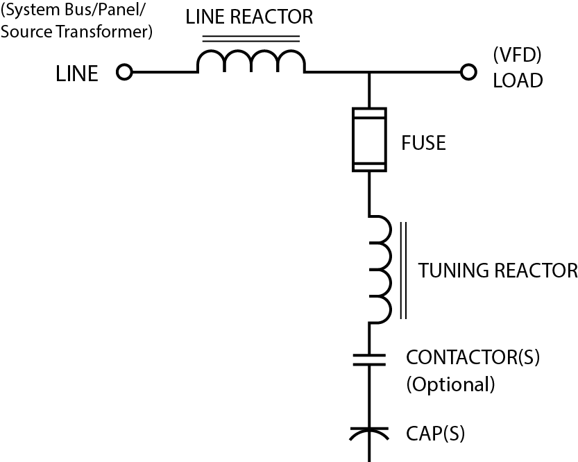
Passive filters create a low-impedance path to ground for the harmonic frequencies and may be tuned to a frequency between two prevalent harmonics to help attenuate both. In addition, they normally include a large line reactor on the input. These filters work well in many applications to help achieve IEEE519 compliance. Due to the capacitors inside of them, care should be taken in application to use the fusing and contactors to protect the lift and remove them from the line when the VFD is not running. These work on all PWM drives which make up 99% of drives made today. Due to the way 6-step drives are made, you should consult your filter manufacturer to help you size a filter for one of these drives.
Active Filters
Like what noise cancelling headphones do with sound waves, these filters inject equal and opposite harmonics onto the power system to cancel those generated by the other equipment. This method has proven effective in reducing harmonics well below required levels. The drawback is that this method can be costly.
12 pulse drives
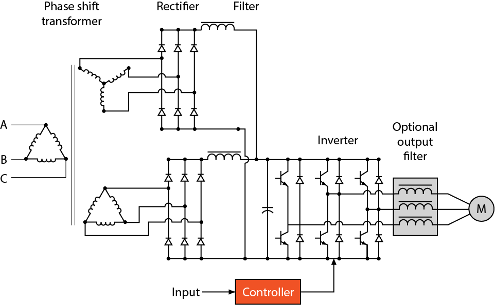
This method employs two separate rectifier bridges, which supply a single DC bus. The two bridges are fed from phase shifted supplies of the output of special transformers. These transformers must be installed to create 6 phases from the 3 utility phases and the phase shifting causes some lower order harmonics to cancel out each other. This method however, is highly sensitive to voltage imbalance as well as background distortion. In addition, if they are lightly loaded, 12 pulse drives still have quite high harmonics. While they are a proven technology, the reality is that 12 pulse drives cannot be counted on to meet IEEE519 in many cases.
18 pulse drives
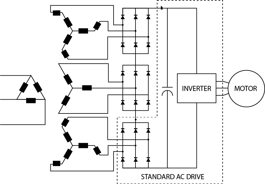
This method employs three separate rectifier bridges, which supply a single DC bus. These bridges are fed from a special transformer that supplies three phase shifted sets of three phase power. This method is effective in eliminating a much wider range of harmonics than the 12-pulse. These transformers are often air-cooled with fans that can be problematic for outdoor applications due to dust and dirt contamination. Another drawback of this method is that voltage imbalances greatly exasperate harmonics. 18 pulse drives have similar harmonic mitigation to the high-performance filters and normally can help meet IEEE519 standards.
Active Front End
This method uses a bidirectional power converter for the front end of a common DC bus drive line up. An external LCL filter is used at the input. This method reduces total harmonics to 2-3% and is immune to voltage imbalances. Active front end is by far the most effective means at reducing harmonics. In addition, active front end drives can boost voltage inside the drive, countering poor power that may exist on site. The drawback of this method is that it is expensive.


