Variable frequency drives (VFDs) are the proven solution for controlling the electric motors that power industry. VFD's enable any process to run at peak efficiency and reliability while saving energy. The opportunity cost with VFDs is the generation of harmonic currents.

Harmonics are distortions of voltage and current that occur when a rectifier is used to convert AC to DC as occurs with a VFD. IEE-519-2014 sets the standard for harmonic distortion limits, but each utility company will set specific limits for their customers.
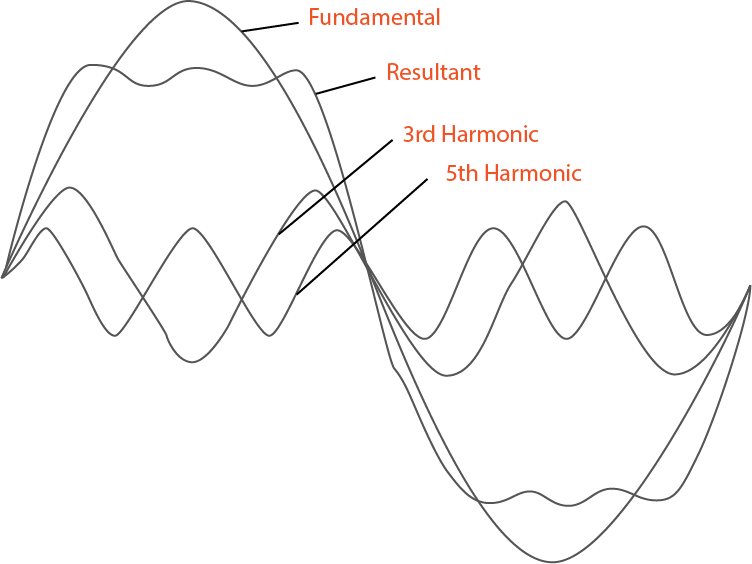
Harmonics explained in the simplest terms are multiples of the utility frequency.
In North America, the utility delivers power at 60Hz. Harmonics are simply electrical currents that occur at multiples of 60Hz. They are described as the numerical multiple, such as the 3rd (180Hz), the 5th (300HZ). All else being equal, the higher the harmonic, the more damage and disruption it's presence can cause. IEEE519-2014 recognizes this and lower amounts of higher harmonics are permitted in the standard.
Harmonic distortion, when allowed to propagate across the grid, can lead to unreliable grid infrastructure, equipment damage, costly fees, or even service termination by the utility company. Additionally, harmonic currents increase energy costs and unwanted heat which reduces the life of power distribution equipment.
For all of these reasons, all VFD installations should include appropriate levels of harmonic mitigation.
Harmonic mitigation solutions vary in their cost, complexity, and suitability for a particular harmonic condition. While some techniques are technically applicable at every size, the economics, complexity, and physical size may favor some types of solutions in various sizes and types of applications. This makes it important to understand the pros and cons of each method. For many situation, more than one technique could be applied to meet utility provider requirements.
6 Harmonic Mitigation Solutions
SOLUTION #1
Inductive Reactance
Inductive reactors are the first option in delating with harmonic distortion.
Reactors resist rapid changes in current which stabilizes the current, and significantly reduces harmonic currents. They are most effective at reducing higher-order harmonics above the 7th order.
Because reactors also introduce an impedance, there is a slight voltage drop across them. This voltage drop and the diminishing returns that come with higher reactance, limit the amount of reactance we can use. A three percent reactor is considered the standard. In practice, some companies request 5% reactor, but the improvement in harmonic mitigation is negligible unless there is a certain problem with higher-order harmonics that is being solved.

A 3% choke on a 100 HP drive, provides 43% reduction in THD, and a 21% reduction in total current.
Reactors can be implemented on the line side (AC Reactor) or the DC Bus of the drive (DC Reactor). From a harmonics mitigation standpoint, there is no practical difference between the two. However, the AC or Line Reactor, as it is often referred to, has the advantage of providing a level of protection for the rectifier from line-side disturbances. The DC reactor offers no such protection.
While inductive reactors are generally not a complete solution to harmonic issues, the low cost, simplicity, increased efficiency, and added protection of AC line reactors make them the recommended first step for all drives of every size.
SOLUTION #2
Passive Harmonic Filters
Passive harmonic filters are the next step form an inductive reactor in cost, complexity, and effectiveness.

The passive filter works by providing a low-impedance path-to-ground for the particular harmonic frequencies it is is tuned for. It consists of a primary inductor with relatively high impedance as well as a shunt-tuned reactor which is in series with capacitors.
The tuned reactor is designed to allow higher frequencies to pass through it and into the capacitors which capture the harmonic currents keeping them off the grid, while the fundamental current continues unabated.
Typically, the passive filter is tuned to as a notch filter capturing both the 5th and 7th harmonics, where the line reactor is ineffectual and the higher impedance primary reactor blocks higher-order harmonics.
Passive filters require careful design based on the harmonic situation at the installation site. Some designs are sensitive to background distortion and are not suitable for these installations. Other designs need to be derated, typically 1-2% per 1% of background THD. Contractors that disconnect the caps when the drive is off should be installed to extend the life of the capacitors and to prevent causing a leading power factor that can create elevated voltages. It is also recommended to install fuses on the caps so that production can continue in the event of capacitor failure.
When expertly designed and installed, passive filters are a cost-effective solution that can be very successful in reducing harmonic distortion to below regulatory limits. As a bonus, passive filters can improve power factor, operating efficiency, and extend the life of your equipment.
SOLUTION #3
Active Harmonic Filters
The active harmonic filter is so named because it uses smart technology to actively and continuously monitor the line inputs to measure incoming harmonic distortion.
It then responds by injecting current equal in amplitude and frequency, but opposite in phase to the harmonic frequencies that are present.
In this way, the harmonics are canceled out, leaving only the fundamental frequency. Active filters are very effective at reducing harmonics form the 50th and below, reducing total harmonic distortion (THD) to around 5% in most cases.
These unites are robust and able to respond to changing harmonic distortion levels, however, because they are powered devices that inject. urrent into the system, they must be rated to ahndle the level of current required. The active filters will not be overloaded, but will only supply harmonic correcting current up to their maximum rating. Because active filters are connected in parallel, it is possible to correct the harmonics for multiple drives, if the limits stay below the rating of the filter. To increase the current handling capacity, multiple filters can be connected in parallel.
Another advantage of the parallel connection of active filters is that the filter location can be more flexible. This makes active filters a great choice for bringing existing pumps into compliance without modifying the existing equipment.
The active filter is a robust, but complex and expensive technology that can reduce harmonic distortion to well below IEE-519 limits. The devices do generate high-frequency noise that requires a passive LCL filter to mitigate. The main drawback of this technology is that per amp it is the most expensive corrective technique. In the future, as the technology improves and manufacturing costs decrease, active harmonic filters are likely to become more common.
SOLUTION #4
12-Pulse Drives
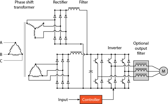
A 12-pulse draw current through a special phase-shifting transformer to power a second 6 diode rectifier.

Standard VFDs use a 6 pulse full-wave rectifier to supply the DC bus. The rectifier and the intermittent current draw that it employs per phase is the primary source of harmonics. A 12-pulse drive draw current through a special phase-shifting transformer to power a second 6 diode rectifier.
The current supplied to the second rectifier is phase-shifted 30 degrees, which causes harmonic currents to cancel each other out. It is especially effective with those of the 5th and 7th orders.
12-pulse drives can reduce THD to around 10%-15% under ideal conditions, which may not meet IEE-519 standards. When voltage imbalances are present between phases, the effectiveness of the harmonic dampening is greatly reduced, and the performance is further reduced when the system is not highly loaded.
The phase-shifting transformer required for the 12-pulse drive is large, very expensive, and requires additional wiring for installation. The drive will still likely need further mitigation techniques to comply with standards. 12-pulse drives a technology that has been surpassed by newer, more cost-effective techniques.
SOLUTION #5
18-Pulse Drives
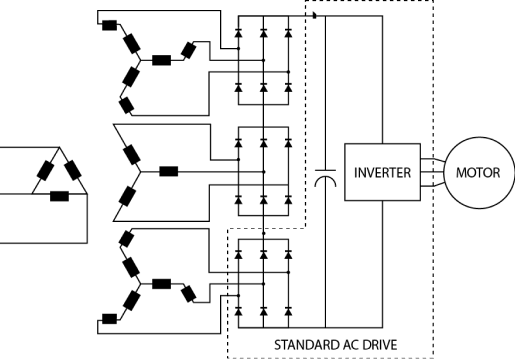
Using the phase-shifting technology of the 12-pulse drive, but taking it to another level is the 18-pulse drive.

The 18-pulse drive uses an even more expensive phase-shifting transformer to power 3 separate 6-pulse rectifiers that are 20° apart.
This cancels the 5th through the 13th harmonics and is able in theory to eliminate the harmonics for the 5th through 13th and reduce the THD to around 5%.
Under ideal conditions, the 18-pulse drive can deliver results that meet IEEE-519 standards. However, like the 12-pulse, the harmonic performance is tied to the phase to phase voltage balance and the loading of the drive. If either of those conditions is less than ideal, the harmonic mitigation performance of the drive will deteriorate significantly. Additionally, the special transformer that powers the drive requires forced air cooling which necessitates regular maintenance to remove dirt build-up around the transformer. The expensive transformer and the forced-air cooling it requires, make the 18-pulse drive a poor fit for dirty environments such as the oil field.
SOLUTION #6
Active Front End Drives
The active front-end drive (AFE) uses a unique approach to harmonic mitigation by eliminating the rectifier, which is the primary source of the harmonics.

The AFE instead uses an inverter bridge made up of insulated gate bipolar transistors (IGBTs.) IGBTS are high-speed electronic switches. These same switches are the same type the drive uses to create the AC current that regulates the speed of the motor, so the AFE essentially consists of two drives. The AFE controls the input IGBTs so that a clean sinewave is drawn from and output back to the mains, and yields a THD as slow as 2-3% for harmonics in the 3rd to 50th range, which is well below IEEE-519 standards.
Unlike the multi-pulse drives, AFEs are immune to voltage imbalances and can achieve excellent results at any load level.
Currently, AFEs are the only technology that can provide a voltage boost for the DC bus when needed. Other benefits include being able to achieve unity power factor and handle regenerative power.
AFEs are available in all sizes up to 2000 hp, but their cost makes them a more economical choice at 100 HP and higher. Because this technology is built into the drive, AFE's are not a retrofit solution. An LCL filter is required to reduce high-frequency noise generated by the input IGBTs.
Harmonic distortion is a complex issue for which there are several mitigation methods as discussed above. The correct choice for correcting a given harmonic issue will depend on many different parameters including the budget, the size of the drive, the levels of THD present, and the required level of harmonic mitigation.


